
Thank you for using RCElectricParts.com's CLASSIC ESC designed to meet your hobby's needs. As you'll find, our the ESC's settings are changeable (programmable, as the industry calls it) with many features. However, the CLASSIC ESCs are plug-and-play and do not need to be programmed to work.
If you have any issues or questions with our product, email us at [email protected] or through our contact form on our website, www.RCElectricParts.com/contact, and we'll be happy to help you!
If you have any issues or questions with our product, email us at [email protected] or through our contact form on our website, www.RCElectricParts.com/contact, and we'll be happy to help you!
Table of Contents |
|
- 02 Product Specification
- 03 Wiring Diagram
- 04 First-time Use | Throttle Range Calibration
- 05 Normal Start up Procedure
- 06 How to Change the ESC's Settings (Programming)
- 07 Programmable Settings
- 08 ESC Safety Features and Protections
- 09 Safety Information
- 10 Using and Arduino or Microcontroller to Control the ESC
- 11 FAQs
01 Main Features |
|
CLASSIC ESC Series
- Plug-and-play
- Programmable settings that adapt to your needs. See How to Change the ESC's Settings (Programming) and Programmable Settings for more information.
- Uses a powerful high-performance microcontroller processor, which provides several of the listed features.
- Supports high RPM motors. See Product Specifications for more information.
- Maintains a constant motor speed.
- Reduces electromagnetic interference signal input using a toroidal ferromagnetic core (green donut with the signal wire wrapped through it).
- Calibrate starting motor throttle position. See First-time Use - Throttle Range Calibration for more information.
- Quick, linear, and stable throttle response that maintains a constant motor speed.
- Integrated SBEC/UBEC provides high current efficiency with minimal heat loss compared to a standard BEC. See Product Specifications for more information.
- Built-in Safety Features: See the ESC Safety Features and Protections section for more information for each safety feature.
- Start up Protection - The ESC will stop powering the motor if it detects the motor is unable to spin after start up.
- Safe Start Protection - The ESC will not power the motor on start up unless the throttle is in the minimum throttle position to prevent dangerous accidental start ups.
- Overheat Protection - Output power reduces to 40% when over 100°C (212°F).
- Lost Signal protection - When signal is lost the ESC cuts the motor's power to prevent a runaway object.
- Low Voltage Protection - If the battery voltage drops below the programmed threshold, the ESC will either shut off or reduce throttle, depending on the programmed setting.
- It can be programmed via the transmitter or using our Programming Card (Sold separately).
- It can be used in model airplanes, drones, helicopters, boats, cars, and other applications where a brushless motor needs to be controlled.
- The ESC beeps during start up to confirm the number of battery cells.
02 Product Specifications |
|
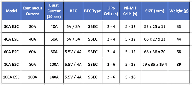
*Size and weight are for reference and may var
Word Definitions
BEC: stand for "Battery Eliminator Circuit" A BEC is an extra circuit in the ESC that eliminates the need to power receivers and servos with another battery. Since these components use a lower voltage (5v) than the ESCs input voltage, standard BECs use a linear regulator that steps down voltage by converting the voltage into heat. The higher the battery voltage, the more heat generated and the less effective the BEC is. Due to this inefficiency, our ESCs use an SBEC/UBEC, which is a more efficient BEC, as explained below.
SBEC (Switching Battery Eliminator Circuit) uses an efficient switching regulator to step down the voltage and doesn't convert the difference in voltage to wasted heat. SBECs are an improved design of BECs.
UBEC: Another name for SBEC
OPTO: The ESC doesn't have a BEC, and a separate power supply is required to power the receiver and other components.
S: Number of cells in a battery, not to be confused with c (charge & discharge rating). Standard LiPo batteries are referenced at 3.7v per cell, which is the average output voltage over the batteries cycle (3.2v dead and 4.2v fully charged)
esc's maximum rpm
ESC's Maximum RPM
480,000 / # poles = maximum RPM, refer to the chart below. The CLASSIC ESC works with almost every motor, so you shouldn't need to worry about this. Rather hook the motor up and see if it works at full speed. Motors spin faster when they are unloaded, so you may find your motor works just fine when the motor is installed in its application. E.g., a propeller is installed.
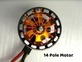
Poles: The number of magnets in the motor.
480,000 / # poles = maximum RPM, refer to the chart below. The CLASSIC ESC works with almost every motor, so you shouldn't need to worry about this. Rather hook the motor up and see if it works at full speed. Motors spin faster when they are unloaded, so you may find your motor works just fine when the motor is installed in its application. E.g., a propeller is installed.
Poles: The number of magnets in the motor.

|
|
advanced explanation about how esc's work
Advanced Explanation
ESCs, take DC power, and output timed AC power to advance the motor's rotation. ESCs have three output wires and switch between a different set of two of the three wires to make a circuit (3-phase AC Power). The ESC can switch the output power up to 480,000 times per second. The more poles (magnets) in the motor, the more times the ESC has to alternate the output power to turn the motor one revolution. Therefore, the maximum RPM the ESC can support is decreased by the number of magnets in the motor.
Kv: Used to calculate the motor's maximum RPM. KV * Input voltage = maximum RPM.
03 Wiring Diagram |
|
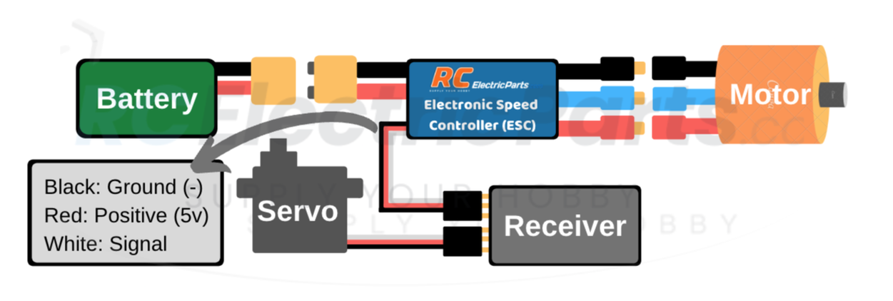
*Ensure all connections and solder joints are adequately insulated and firmly connected without any loose or weak connections.
Reverse Motor Direction
Swap any two connections between the ESC and motor to reverse the motor direction, or you can program the ESC to spin in the reverse direction. See How to Change the ESC's Settings (Programming) for more information.
Reverse Motor Direction
Swap any two connections between the ESC and motor to reverse the motor direction, or you can program the ESC to spin in the reverse direction. See How to Change the ESC's Settings (Programming) for more information.
04 First-time Use | Throttle Range Calibration |
|
The ESC is plug-and-play, and the settings should not need to be changed (programmed). Though, we recommend doing a throttle range calibration to set the minimum and maximum throttle points to ensure smooth and accurate throttle control. If you do want to change the ESC's settings, see How to Change the ESC's Settings (Programming) for more information.
VIDEO INSTRUCTIONS
Diagram Instructions
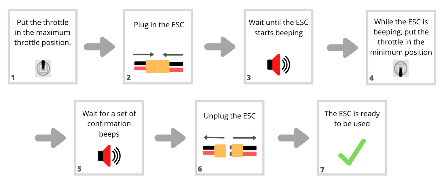
*The diagram above is for general use. Your setup may be different, e.g., if your maximum throttle position is reversed. Refer to the written instructions above the diagram for more detail.
Written Instruction
Throttle Range Calibration Procedure - Written Instructions
Performing the Throttle Range Calibration procedure is recommended when using the ESC for the first time or changing receivers.
Performing the Throttle Range Calibration procedure is recommended when using the ESC for the first time or changing receivers.
- Put the transmitter's throttle in the maximum throttle position.
- Power the ESC.
- Wait about 5 seconds for the motor to start sounding a short beep. The ESC repeats these short beeps a total of four times. WHILE the motor is making these short beeps, proceed to step 3.
- Move the throttle to the minimum throttle position.
- After a few seconds, the motor will make 2 short beeps followed by 2 longer beeps to confirm that the throttle Range Calibration has been complete.
- Power off the ESC.
- The throttle range calibration is complete, and you're good to use the ESC as usual.
05 Normal Start up Procedure |
|
Welcome to the Normal Startup Procedure section of the ESC user manual. In this section, we will guide you through the essential steps for using the ESC, along with an explanation of some different situations and tones you might encounter during operation. By following these instructions, you will ensure a smooth and efficient experience with your ESC.
Video Instructions
diagram instructions
*The diagram above is for general use. Your setup may be different, e.g., if your full throttle position is reversed. Refer to the written instructions below for more detail.
written instructions
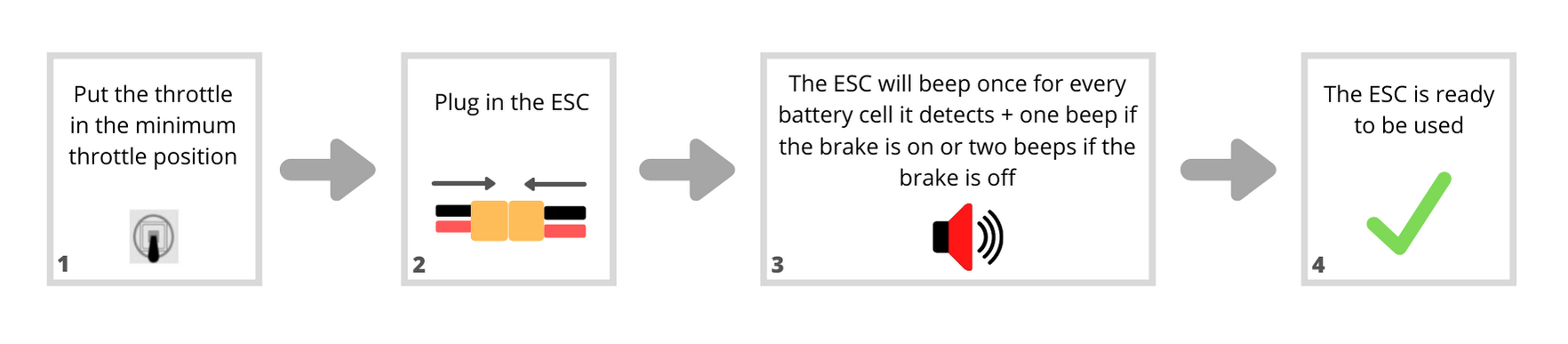
Normal Start up Procedure - Written Instructions
- Put the transmitter's throttle in the minimum throttle position, power on the ESC.
- Plug in the ESC
- If the throttle is partially on, the ESC goes into its Safe Start Protection mode and continually makes rapid short beeps until the throttle is put in the minimum throttle position. See ESC Safety Features & Protections for more information.
- If the throttle is in the full throttle position, the ESC enters into its programming mode and makes several different tones. If this is the case, re-power the ESC with the throttle in the minimum throttle position. See How to Change the ESC's Settings (Programming) for more information.
- The ESC makes a series of short beeps.
- The first set of beeps indicates the number of cells the ESC detects in the battery. E.g., 3 beeps indicate a 3 cell battery. (You can change the ESCs battery-type setting if needed. The default is LiPo. See Programming Instructions for more information).
- The second set of beeps indicates the brake setting. Single beep if the brake is on or a double deep if the brake is off.
- The ESC is ready to be used.
06 How to change the ESC Settings (Programming) |
|
The CLASSIC ESC series is designed as plug-and-play, requiring no programming to function. However, if you wish to modify the ESC settings, there are two available methods. Method A involves using the transmitter, while Method B requires an RCElectricParts.com's Programming Card. Both methods are effective. Although using the transmitter may seem daunting, we have provided detailed steps below to guide you through the process. Alternatively, using a programming card offers a more straightforward approach but necessitates purchasing an additional device. I personally use the transmitter method.
METHOD A: Changing ESC Settings Using the Transmitter
video instructions
diagram instructions
*See the table of programmable settings above
written instructions
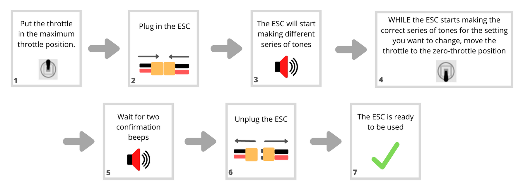
Changing ESC Settings Using the Transmitter - Written Instructions
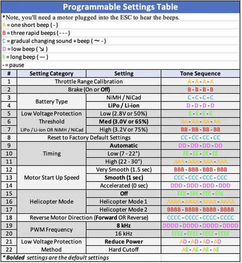
There are five different tones symbolized by a letter, A, B, C, and D. Once the ESC goes into its programming mode, it sequentially goes through the programmable settings, starting with setting #1 and ending on setting #22. To cycle through the settings again, re-power the ESC. To determine which setting is currently selected, listen to the tone sequence. WHILE the ESC is on the desired setting, move the throttle to the minimum position to activate that setting. Poweroff the ESC and follow the Normal Start Up Procedure.
There are five different tones symbolized by a letter, A, B, C, and D. Once the ESC goes into its programming mode, it sequentially goes through the programmable settings, starting with setting #1 and ending on setting #22. To cycle through the settings again, re-power the ESC. To determine which setting is currently selected, listen to the tone sequence. WHILE the ESC is on the desired setting, move the throttle to the minimum position to activate that setting. Poweroff the ESC and follow the Normal Start Up Procedure.
METHOD B: Changing the ESC Settings Using the Programming Card
Programming Card Product Link: Programming Card Link
video instructions
written instructions
Changing ESC Settings Using the Programming Card - Written Instructions
To program the ESC using the programming card is simple. Move the red jumpers to the desired setting, power on the ESC. If connected to a motor, wait for the confirmation beep. If there isn't a motor connected, wait a few seconds. Power down the ESC, and you're done.
To program the ESC using the programming card is simple. Move the red jumpers to the desired setting, power on the ESC. If connected to a motor, wait for the confirmation beep. If there isn't a motor connected, wait a few seconds. Power down the ESC, and you're done.
07 Programmable Settings |
|
Programmable Settings - Breakdown and Explanation
Here is a breakdown of what each setting is. For detailed instructions on how to change the ESC's Settings see How to Change the ESC's Settings (Programmable)
*Underlined settings below are the default settings
Here is a breakdown of what each setting is. For detailed instructions on how to change the ESC's Settings see How to Change the ESC's Settings (Programmable)
*Underlined settings below are the default settings
1. Throttle Range Calibration
1. Throttle Range Calibration: Sets the minimum and maximum throttle points to ensure a smooth and accurate throttle control. See First-time Use - Throttle Range Calibration Procedure for more information.
2. Brake
2. Brake: On, Off
On: The propeller will stop immediately when the throttle stick is moved to the neutral position.
Off: The propeller with be able to freely spin when the throttle stick is moved to the minimum throttle position.
On: The propeller will stop immediately when the throttle stick is moved to the neutral position.
Off: The propeller with be able to freely spin when the throttle stick is moved to the minimum throttle position.
3 - 4. Battery Type:
3 - 4. Battery Type: NiMH / NiCad, LiPo / Li-ion
3. NiMH / NiCad: Sets the battery type and is used in conjunction with Low Voltage Protection Threshold and Low Voltage Protection Cutoff settings. Selecting this setting will reset the Low Voltage Protection Threshold setting to "65%".
4. LiPo / Li-ion: Sets the battery type and is used in conjunction with Low Voltage Protection Threshold and Low Voltage Protection Cutoff settings. The Low Voltage Protection Threshold setting will not be affected by selecting the LiPo / Li-ion setting.
5 - 7. LOW VOLTAGE PROTECTION THRESHOLD:
5 - 7. Low Voltage Protection Threshold: Low (2.8V or 50%), Medium (3.0V or 65%), High (3.2V or 75%)
Sets the voltage point at which to activate the Low Voltage Protection Method setting. See Low Voltage Protection for more information and ensure the Battery Type setting is correct (LiPo / Li-ion is the default)
5. Low (2.8V or 50%): Sets the voltage threshold point at 2.8 volts for LiPo / Li-ion batteries and 50% initial battery voltage for NiMh / NiCad batteries.
6. Medium (3.0V or 65%): Sets the voltage threshold point at 3.0 volts for LiPo / Li-ion batteries and 65% initial battery voltage for NiMh / NiCad batteries.
7. High (3.2V or 75%): Sets the voltage threshold point at 3.2 volts for LiPo / Li-ion batteries and 75% initial battery voltage for NiMh / NiCad batteries.
8. Reset to Factory Default Settings
8. Reset to Factory Default Settings
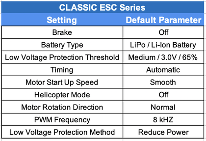
Factory default settings are as follows:
Factory default settings are as follows:
9 - 11. Timing
9 - 11. Timing: Automatic, Low, High
9. Automatic: The ESC automatically detects the most suitable motor timing.
10. Low (7 – 22 degrees): Suitable for most inrunner motors.
11. High (22 – 30 degrees): Suitable for most outrunner motors.
*Note: We recommend using "Automatic" timing. Efficiency can be increased for 2 pole inrunner motors by settings the timing to low and for 6 pole outrunner motors by setting the timing to high. Power can sometimes be increased for outrunner motors by setting the timing to high at the cost of efficiency and excess motor heat.
12 - 14. Motor Start up Speed
12 - 14. Motor Start up Speed: Very Smooth, Smooth, Accelerated Start up
12. Very Smooth: 1.5-second linear throttle lag response time between starting the motor and full motor speed. This setting is excellent for preventing gearboxes from stripping from starting up too fast.
13. Smooth: 1-second linear throttle lag response time between starting the motor and full motor speed. This setting is recommended for geared motors or slower start ups.
14. Accelerated: 0-second throttle lag response time between starting the motor and full motor speed. This setting is recommended for direct-drive motors and responsive throttle control.
15 - 17. Helicopter Modes
15 - 17. Helicopter Modes: Off, Mode 1, Mode 2
15. Off: Turns off Helicopter Mode.
16. Helicopter Mode 1: Delays throttle response time between zero-throttle position and full-throttle position by 5 seconds.
17. Helicopter Mode 2: Delays throttle response time between zero-throttle position and full-throttle position by 15 seconds.
*Note: Helicopter Mode is slightly different than "start up speed" as it only delays the throttle lag response time when the throttle is in the zero-throttle position for a few seconds and then when the throttle is applied. Otherwise, the throttle will respond according to the programmed "start up speed" parameter.
**Note: If the Helicopter Mode is turned on, the Brake setting will be reset to "Off", and the Low Voltage Protection Method setting will be reset to "Reduce Power".
18. Motor Rotation Direction
18. Motor Rotation Direction: Forward, Reverse
18. Forward OR Reverse: Changes the motor direction to be either forward OR reverse. Not forward AND reverse as that requires a bi-directional ESC and the CLASSIC ESC series are uni-directional ESCs.
*Note: The motor's rotation direction can also be reversed by swapping any two of the three connections between the motor and ESC. The Motor Rotation Direction setting is helpful if the connection between the motor and ESC is hard to get to or soldered.
19 - 20. PWM Frequency
19 - 20. PWM Frequency: 8kHz, 16kHz
19. 8kHz: Output Frequency to the motor. Generally used for inrunner motors with lower pole counts, more power-efficient, causes less Electromagnetic Interference (EMI), and is the ESC's default setting.
20. 16kHz: Output Frequency to the motor. PWM frequency is generally used for outrunner motors because the motor will run smoother and with slightly more power but at the cost of the ESC running hotter causing more Electromagnetic Interference (EMI).
21 - 22. Low Voltage Protection Method
21 - 22. Low Voltage Protection Method: Reduce Power, Hard Cutoff
21. Reduce Power: The ESC will reduce the motor's output power when the set Low Voltage Protection Threshold is reached to protect the battery from over-discharging but still provides enough power to return the craft. This parameter is recommended.
22. Hard Cutoff: The ESC will completely shut off the motor's output power when the set Low Voltage Protection Threshold is reached to protect the battery from over-discharging.
08 ESC Safety Features and Protections |
|
Start up Protection
The ESC will stop the motor if the motor fails to spin within two seconds after applying the throttle. Possible situations that would cause this fault are: The motor or propeller cannot freely rotate, a connection between the motor and ESC, or an electrical short in the motor.
Safe Start Protection
Safe Start Protection helps prevent unexpected motor startups. If throttle input is applied before the ESC powers on, the ESC will not power on the motor. Instead, it will emit rapid beeps until the throttle is returned to the minimum position. Once the throttle is in the minimum position, the ESC will continue its startup procedure as usual.
Overheat Protection
If the ESC gets hotter than 212 °F (100 ℃), the ESC will limit the output power to 40% to prevent the ESC from becoming damaged without shutting off all power output during operation. Once the ESC's temperature reaches operating temperature, the ESC will work as usual.
Signal Protection
If the receiver losses signal for more than two continuous seconds, the ESC will reduce power. If the lost signal continues for more than four seconds, the ESC will gradually shut off power to the motor, preventing a runaway object.
Low Voltage Protection
The warning tone: The warning tone is set as an audible sound to help users judge abnormal conditions after turning on the power. 1. Fail to enter working mode after turning on the power: the routine of the throttle has not been set yet. 2. Continuing beeps: the pull rod of the throttle is not in the lowest position. 3. There is a short pause after a beep: the ESC can not detect normal throttle signals from the receiver. 4. There is a pause of one second after a beep: the voltage of the battery pack is out of acceptable limit (once the battery is connected, the ESC will carry out a self-checking and check the voltage of the battery.)
09 Safety Information |
|
DO
DO NOT
- Remove the propeller from the motor when programming or using the ESC for the first time.
- Use a battery that is in good condition and rated above the maximum current draw of the motor.
- Use a battery that is within the cell/voltage range of the ESC.
- If using new connectors, make sure the battery polarities are correct. Reversing the polarity will destroy the ESC. I.e., red (+) to red (+) and black (-) to black (-).
- Install ESC with good ventilation so heat can dissipate.
DO NOT
- Do not overload the SBEC by using too many or too big servos and other components. Drawing too many amps will cause the SBEC voltage to drop (brownout) and may cause the receiver to reboot during use.
- Do not get the ESC wet.
- Do not unplug the battery while the motor is spinning.
10 Using and Arduino or Microcontroller to Control the ESC |
|
The video listed below is very information and is recommended you start there.
*Jump to about 8 min 40 sec into the video for information about ESCs
Thanks to How to Mechatronics for a thorough explanation of how an ESC works.
Electronic Speed Controller (ESC) Input Signal
The ESC utilizes a standard PWM signal for control. Details are as follows:
PWM Signal Frequency: 50 Hz
Throttle Control:
The PWM signal operates on a spectrum between these endpoints, allowing for incremental control of the throttle between 1 ms (zero throttle) and 2 ms (full throttle).
The ESC utilizes a standard PWM signal for control. Details are as follows:
PWM Signal Frequency: 50 Hz
Throttle Control:
- 1 ms pulse width: Zero throttle
- 2 ms pulse width: Full throttle
The PWM signal operates on a spectrum between these endpoints, allowing for incremental control of the throttle between 1 ms (zero throttle) and 2 ms (full throttle).
11 FAQs |
|
Does this work with brushed motors?
A: No, this ESC is designed specifically for brushless motors
The motor makes a rapid succession of beeps on start up.
A: The ESC has entered into its Safe Start Protection mode to prevent the motor from unexpectedly rotating and will rapidly beep letting you know the throttle is part way on. Once the throttle is put into the minimum throttle position, the ESC will make the start up confirmation beeps and will work as normal.
If putting the throttle in the minimum throttle position doesn't fix the issue, you'll need to do a "Throttle Range Calibration". See First-time Use set the minimum and maximum points on the throttle range.
Note, our CLASSIC Series ESC is Uni-directional meaning it'll only spin the motor in one direction. If you needing a bi-directional ESC, trying to spin the motor in both direction and have a controller with the neutral throttle in the center, you'll need our DEFIANT Series ESC that has our Multi-directional technology allowing the ESC to be set either as a Uni-directional or Bi-directional.
Can the ESC run in forward and reverse?
A: The ESC is a uni-directional ESC designed to run the motor only in one direction during operation. The ESC has a programmable setting to reverse the motor direction, so you do not have to swap any two of the three motor wires to reverse the motor direction manually.
If you need a bi-directional ESC. Check out our DEFIANT ESC Series that can be either a Uni-directional or Bi-directional ESC.
If you need a bi-directional ESC. Check out our DEFIANT ESC Series that can be either a Uni-directional or Bi-directional ESC.
The motor spins in wrong direction. How do I reverse the motor direction?
There are two option. Swap any two of the three motor plugs or, if it is easier, program the ESC to run in the opposite direction. See programming instructions above.
How to connect MULTIPLE motors?
To connect multiple motors to a single set up. Here is the process.
- Each motor needs its own ESC. One ESC cannot control. Multiple motors as the ESC dynamically changes its timing to sync with the motor.
- Connect all the ESC's to the signal output on the receiver/controller using a servo splitter.
- Perform a throttle calibration procedure to sync the ESC starting position and range. First-time Use - Throttle Range Calibration